팔콘 밴드쏘와 메뉴얼
안녕하세요.
오늘은 팔콘 밴드쏘와 매뉴얼에 대해서 알아보겠습니다.
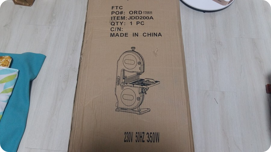
매뉴얼이 있긴 있는데, 영문 매뉴얼뿐입니다. 부족하지만 나름 번역해 보았습니다. 혹 도움이 될까 해서 올립니다.
V. Know your band saw
V. 밴드쏘 알기

Cover 커버 Cover knob 커버 손잡이 Cover hinges 커버 경첩 Blade guard 톱날 가드
Fence 펜스 Blade guide 톱날 유도장치 Switch key 스위치 키 Blade 톱날
On/Off switch 온오프 스위치 Mitre gauge 연귀 계측기 Zero stop set screw ? 나사
Table aligning screw 테이블 정렬 나사 Sawdust ejection port 톱밥 배출 포트
Cover knob 커버 손잡이 Mounting holes 장착 구멍
Blade tension adjustment knob 톱날 장력 조정 손잡이
Tracking adjustment knob 트래킹(추적) 조정 손잡이
Upper slide adjusting knob 상단 슬라이드 조정 손잡이
Table 테이블 Trunnion 트러니언 Tilt scale 기울기 척도
Table lock handle 테이블 잠금 핸들 Tilt pointer 기울기 포인터 Base 베이스
Hex key wrenches - 2 육각 렌치

저건 뭔지 모르겠습니다???
Blade guides support the blade and keep it from twisting during operation. Blade guides must be adjusted when blade is changed or replaced.
블레이드 가이드는 블레이드를 지원하고 작동 중 비틀림을 방지합니다. 블레이드를 교체하거나 재조정할 때 블레이드 가이드를 조정해야 합니다.
Upper slide adjusting knob locks the upper slide. Use it after you adjust the upper guide assembly to make sure upper blade guide just clears workpiece before cutting. Upper slide adjusting knob must be tightened before the band saw is turned on.
상단 슬라이드 조절 손잡이는 상단 슬라이드를 잠급니다. 상부 가이드 조립체를 조정한 후에 상단 톱날 가이드가 절단하기 전에 공작물을 깨끗하게 정리할 수 있도록 하십시오. 밴드쏘가 켜지기 전에 상단 슬라이드 조절 노브를 조여야 합니다.
Table lock handle locks the table in place.
테이블 잠금 핸들은 테이블을 제자리에 고정시킵니다.
Tilt (bevel) scale shows the degree the table is tilted for bevel cutting.
기울기 (경사) 눈금은 테이블이 경사 절단을 위해 기울어진 정도를 나타냅니다.
Blade tension adjustment knob controls the amount of blade tension when changing blades.
톱날 장력 조정 노브는 톱날을 교체할 때 톱날 장력의 양을 제어합니다.
Tracking adjustment knob adjusts blade position so blade always runs in the centre of the wheel.
추적 조정 손잡이는 톱날 위치를 조정하여 톱날이 항상 휠 중앙에서 작동하도록 합니다.
Sawdust ejection port helps keep the machine free from sawdust. The sawdust ejection port makes an excellent hook-up for a wet/dry vacuum.
톱밥 배출 포트는 기계에 톱밥이 들어가지 않도록 합니다. 톱밥 분출 포트는 습식/건식 진공을 위한 훌륭한 연결 장치입니다.
Switch has a built-in child safety lock. To lock the switch in the 'off' position, remove the switch key from the switch.
스위치에 아동 안전장치가 내장되어 있습니다. 스위치를 '오프' 위치에 잠그려면 스위치 키를 스위치에서 제거합니다.
VI. Assembly and adjustments
VI. 조립 및 조정
Unpacking
개봉
1. Carefully remove the band saw from the carton.
1. 상자에서 밴드쏘를 조심스럽게 제거하십시오.
2. Separate the parts.
2. 부품을 분리하십시오.
3. Lay out all the parts and check them against the parts listed.
3. 모든 부품을 배치하고 나열된 부품과 대조하여 확인하십시오.
WARNING : If any part is missing or damaged, do not plug the band saw in until you have replaced the missing or damaged part.
경고 : 빠진 부분이나 손상된 부분이 있는 경우, 빠진 부분이나 손상된 부분을 교체할 때까지 밴드 쏘를 연결하지 마십시오.

Fig.1
Band saw, Fence, Saw table, Mitre gauge, Table lock handle, Hex key wrenches
밴드쏘, 펜스, 쏘테이블, 연귀 계측기, 테이블 잠금 손잡이, 육각 렌치
ASSEMBLING
조립하기
Saw table (Fig.2)
쏘테이블(그림 2)
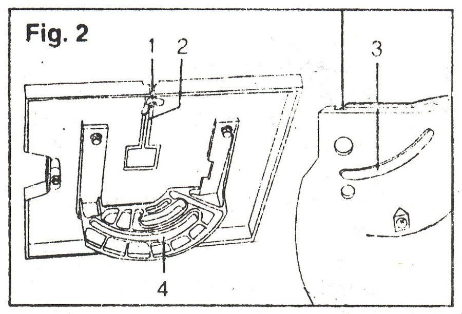
1. Remove the table aligning screw and nut (1) from the table edge.
1. 테이블 모서리에서 테이블 정렬 스크류(나사)와 너트 (1)를 제거하십시오.
2. Place the table onto the saw. Slide the blade through the table slot (2). Make sure the mounting rib (3) on the side of the housing is engaged with the recessed groove on the trunnion bracket (4).
2. 테이블을 톱 위에 올려놓습니다. 톱날을 테이블 슬롯 (2)에 밀어 넣으십시오. 하우징 측면의 장착 리브 (3)가 트러니온 브래킷 (4)의 오목한 홈에 맞물리도록 하십시오.
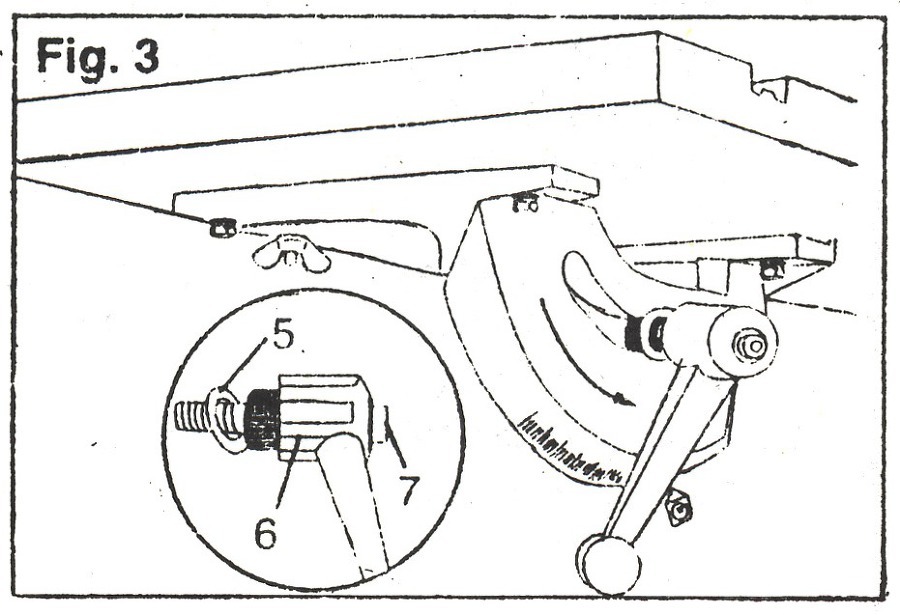
3. Slide the flat washer (5) (Fig.3) on to the threaded end of the handle (6). Tighten the table to the housing by turning the handle.
3. 평평한 와셔 (5) (그림 3)를 핸들 (6)의 나사산 끝 부분으로 밀어 넣으십시오. 손잡이를 돌려서 테이블을 하우징에 조입니다.
4. Replace the aligning screw and nut (1).
4. 정렬 나사와 너트를 다시 끼웁니다.
NOTE : The spring loaded handle (6) is released by pulling the handle back towards the screw head (7).
참고 : 스프링 장착 손잡이 (6)는 손잡이를 나사 머리 (7) 쪽으로 뒤로 잡아당겨서 분리합니다.
5. If necessary, adjust the tilt pointer to reflect actual table tilt position.
5. 필요한 경우, 기울기 포인터를 조정하여 실제 테이블 경사 위치를 조정합니다.
Mounting to work surface (Fig.4)
작업대에 장착하기(그림 4)

1. Band saw 밴드쏘 2. Hex head bolt 육각 헤드 볼트 3. Flat washer 와셔
4. Washer 와셔 5. Workbench 작업대 6. Flat washer 와셔
7. Lock washer 와셔 8. Hex nut 육각 너트 9. Jamb nut 너트
1. If the saw is to be used in a permanent location it must be secured to a supporting surface, such as a work bench.
1. 밴드쏘를 영구적인 장소에서 사용하려면 작업대와 같은 지지 표면에 고정해야 합니다.
2. The four predrilled holes in the base of the saw are to be used for permanent mounting.
2. 밴드쏘 하단에 있는 4 개의 구멍은 영구적인 장착에 사용됩니다.
Opening and closing of the housing door (Fig.5)
하우징 도어의 개폐 (그림 5)
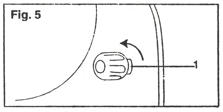
1. Turn the lock knobs (1) counterclockwise to open.
1. 잠금 노브(손잡이) (1)를 시계 반대 방향으로 돌려 엽니다.
2. Loosen both knobs to open the cover.
2. 양쪽 손잡이를 풀어 덮개(커버)를 엽니다.
3. Close the cover, tighten lock knobs clockwise.
3. 덮개를 닫고 잠금장치 손잡이를 시계 방향으로 조입니다.
WARNING : Turn saw off, remove the switch key, and unplug the saw before removing, adjusting, or installing the blade.
경고 : 톱날을 제거, 조정 또는 설치하기 전에 밴드쏘를 끄고 스위치 키를 제거한 다음, 플러그를 뽑으십시오.
Replacing the blade (Fig.6)
톱날 교체 (그림 6)
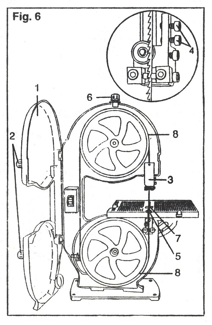
1. Unlock the hinged housing cover (1) by loosening the two knobs (2) and pulling the cover open.
1. 두 개의 손잡이 (2)를 풀고 덮개를 당겨 여닫이형 하우징 덮개 (1)를 엽니다.
2. Loosen the blade guard (3) and position it about halfway above the table. Tighten the knob.
2. 톱날 보호대 (3)를 풀고 테이블 위 약 절반 정도 위치시킵니다. 손잡이를 조입니다.
3. Loosen the two blade guard mounting screws (4) with the hex key and remove the blade guard (3).
3. 육각형 키로 톱날 보호대 고정 나사 (4) 2 개를 풀고 톱날 보호 장치 (3)를 분리합니다.
4. Remove the table aligning screw (5) from the table.
4. 테이블에서 테이블 정렬 나사 (5)를 제거합니다.
5. Turn the blade tension knob (6) counterclockwise to loosen the blade tension.
5. 톱날 장력 조절기 (6)를 시계 반대 방향으로 돌려 톱날 장력을 느슨하게 합니다.
6. Slide the blade through the table slot (7).
6. 톱날을 테이블 슬롯 (7)에 밀어 넣습니다.
7. Install the replacement blade with the teeth pointing forward and down. (see Fig.7)
7. 톱니를 앞뒤로 향하게 하여 교체 톱날을 설치하십시오. (도 7 참조)
8. Centre the blade on the upper and lower wheels (8).
8. 톱날을 상하 휠에 센터링합니다 (8).
9. Rotate the wheels clockwise to help guide the blade on to the wheels. Tighten the blade tension knob (6).
9. 휠을 시계 방향으로 돌려 톱날을 휠 쪽으로 유도합니다. 톱날 장력 조절 장치 (6)를 조이십시오.
10. Reassemble by following the previous steps in reverse order.
10. 이전 단계를 역순으로 다시 조립하십시오.
Adjusting
조절하기
Blade tension (Fig.8)
톱날 장력(그림 8)
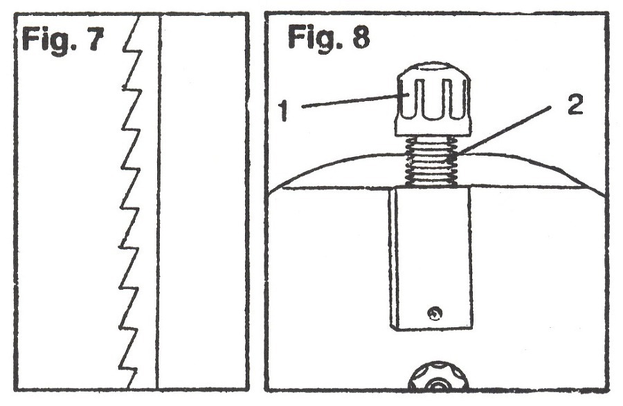
1. When the blade is centred on both wheels, turn the blade tension knob (1) clockwise until you see the spring (2) compressing.
1. 톱날이 양쪽 휠의 중앙에 오게 되면, 스프링 (2)이 압축될 때까지(압축이 보일 때까지) 톱날 장력 조절기 (1)를 시계 방향으로 돌립니다.
2. Continue tightening until the blade is tight on the wheels. Under-tightening the blade will cause it to slip on its wheels.
2. 톱날이 휠에 단단해질 때까지 조입니다. 톱날을 과도하게 조이지 않으면 휠에서 미끄러질 수 있습니다.
3. Do not over-tighten the blade.
3. 톱날을 너무 세게 조이지 마십시오.
WARNING : Turn saw off, remove the switch key, and unplug the saw before removing, adjusting, or installing the blade.
경고 : 톱날을 제거, 조정 또는 설치하기 전에 밴드쏘를 끄고 스위치 키를 제거한 다음, 플러그를 뽑으십시오.
Blade tracking (Fig.9)
톱날 트래킹(추적)(그림 9)
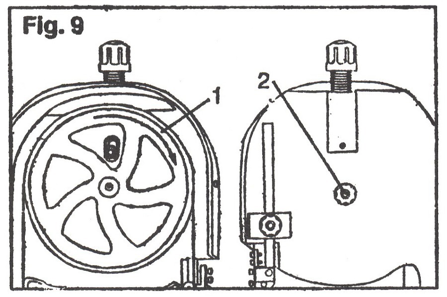
NOTE : Adjust blade tension properly before making tracking adjustments. Check that the blade guides are not interfering with the blade.
참고 : 트래킹(추적) 조정을 수행하기 전에 톱날 장력을 적절하게 조정하십시오. 톱날 가이드가 톱날을 방해하지 않는지 확인하십시오.
1. Turn the upper wheel clockwise (1) and watch the blade on the tire. If the blade moves away from the tire centre, tracking adjustment is required.
1. 위쪽 휠을 시계 방향으로 돌리고 (1) 타이어의 톱날을 보십시오. 톱날이 타이어 중심에서 멀어지면 트래킹 조정이 필요합니다.
2. If the blade moves toward the front side, turn the tracking knob (2) clockwise. At the same time, turn the wheel until the blade returns to the centre of the tire.
2. 톱날이 앞쪽으로 움직이는 경우, 트래킹 노브 (2)를 시계 방향으로 돌립니다. 동시에 톱날이 타이어 중심으로 돌아올 때까지 휠을 돌리십시오.
3. If the blade shifts toward the backside, turn the knob (2) counterclockwise. At the same time, turn the wheel until the blade is centred.
3. 톱날이 뒷면 쪽으로 이동하면 노브 (2)를 반 시계 방향으로 돌립니다. 동시에 톱날이 중앙에 올 때까지 휠을 돌리십시오.
4. Check the position of the blade on the lower wheel. If the tracking is off, adjust it until the blade sits properly on both tires.
4. 하단 휠의 톱날 위치를 확인합니다. 트래킹이 꺼져 있으면 톱날이 양쪽 타이어에 올바르게 장착될 때까지 조정하십시오.
5. Turn the upper wheel clockwise to ensure the blade stays centred on both wheels. If necessary, readjust tracking.
5. 위쪽 휠을 시계 방향으로 돌려 톱날이 양쪽 휠의 중앙에 오도록 합니다. 필요한 경우 트래킹(추적)을 다시 조정하십시오.
Upper blade guard (Fig.10)
상부 톱날 가드(그림 10)

1. Loosen the knob (1) and position the blade guard (2) approximately 1/8″ above the workpiece.
1. 노브 (1)를 풀고 톱날 가드 (2)를 공작물 위에서 대략 1/8" (3미리?) 위치시킵니다.
2. Tighten the knob (1).
2. 손잡이 (1)를 조입니다.
WARNING : Turn saw off, remove the switch key, and unplug the saw before removing, adjusting, or installing the blade.
경고 : 톱날을 제거, 조정 또는 설치하기 전에 밴드쏘를 끄고 스위치 키를 제거한 다음, 플러그를 뽑으십시오.
Blade Guides - Upper (Fig.11)
톱날 가이드 - 상단(그림 11)
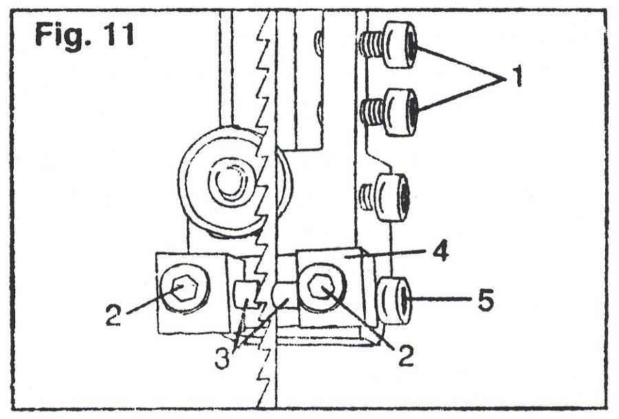
NOTE : The upper and lower blade guides and support bearing keep the blade moving in a straight line during operation. These guides must be checked and adjusted before each use and after blade changes.
참고 : 위쪽 및 아래쪽 톱날 가이드 및 베어링 지지대는 작동 중에 톱날이 직선으로 움직이지 않도록 합니다. 이 가이드는 사용하기 전과 교체 한 후에 점검하고 조정해야 합니다.
1. Remove the blade guard by loosening the two screws (1) with the hex key. Slide the blade guard away from the screws.
1. 육각 키로 2 개의 나사 (1)를 풀어 톱날 가드를 제거합니다. 톱날 보호대(가드)를 나사에서 멀리 밀어 빼내십시오.
2. Loosen the two front screws (2). Adjust the blade guides (3) so they are as close as possible to the blade, without touching or pinching it. Tighten the screws (2).
2. 두 개의 앞면 나사 (2)를 풉니다. 만지거나 가리지 않고 가능한 한 톱날에 가까워지도록 톱날 가이드를 조정하십시오 (3). 나사 (2)를 조입니다.
3. Adjust the blade guide bracket (4) by loosening the screw (5). Move the bracket until the front of the guides (3) are behind the blade teeth. Tighten the screw (5).
3. 나사 (5)를 풀어 톱날 가이드 브래킷 (4)을 조정합니다. 가이드 (3)의 전면이 톱니 아래에 올 때까지 브래킷을 움직입니다. 나사 (5)를 조입니다.
Blade supports - Upper and Lower (Fig.12)
블레이드 지지대 - 상단 및 하단 (그림 12)
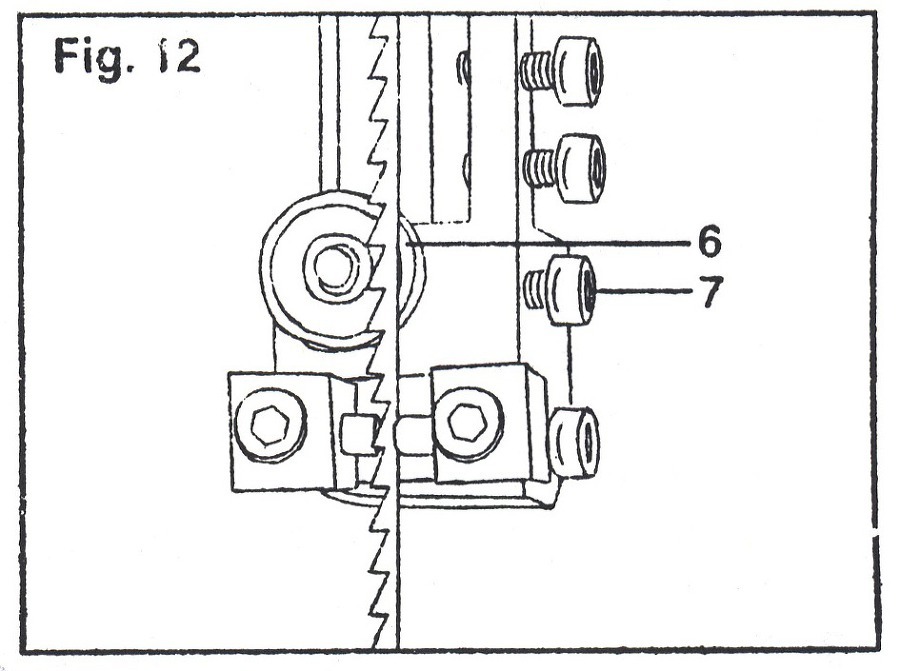
The support bearing (6) keeps the saw blade from being pushed back when it is cutting. The blade should be positioned 1/32″ from the bearing to operate properly.
지지 베어링 (6)은 절단될 때 톱날이 뒤로 밀리는 것을 방지합니다. 톱날은 올바르게 작동하려면 베어링에서 1/32"(0.7미리?) 위치에 있어야 합니다.
1. Loosen the screw (7). Slide the support bearing (6) to 1/32″ from the blade.
1. 나사 (7)를 풉니다. 지지 베어링 (6)을 톱날에서 1/32인치까지 밉니다.
2. Tighten the screw (7).
2. 나사 (7)를 조입니다.
3. Replace the blade guard if no additional adjustments are to be made.
3. 추가 조정을 하지 않을 경우 톱날 보호 장치를 교체하십시오.
4. Repeat this adjustment for the lower support bearing.
4. 하부 지지 베어링에 대해 이 조정을 반복하십시오.
Blade guides and bracket - Lower (Fig.13)
톱날 가이드 및 브래킷 - 하단 (그림 13)
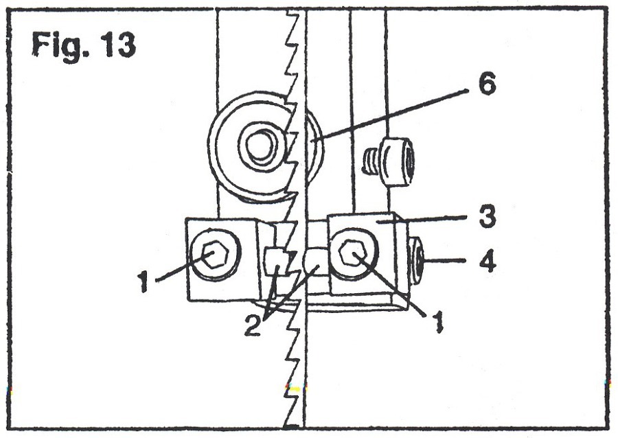
1. Loosen the screws (1) and adjust the guides (2) in the same manner as the upper blade guides. Move the guides (2) as close as possible to the blade without touching or pinching the blade. Tighten the screws (1).
1. 나사 (1)를 풀고 상단 톱날 가이드와 같은 방법으로 가이드 (2)를 조정합니다. 톱날을 만지거나 가리지 않고 가능한 한 가이드 (2)를 톱날에 가깝게 이동합니다. 나사 (1)를 조입니다.
2. Adjust the blade guide bracket (3) by loosening the screw (4). Move the bracket until the front of the guides (2) is behind the blade teeth.
2. 나사 (4)를 풀어 톱날 가이드 브래킷 (3)을 조정합니다. 가이드 (2)의 전면이 톱니 아래에 올 때까지 브래킷을 움직입니다.
3. Tighten the screw (4).
3. 나사 (4)를 조입니다.
NOTE : Make sure you have properly adjusted both the upper and lower blade guides. The blade will be ruined if the blade teeth hit the blade guides.
참고 : 상단 및 하단 톱날 가이드를 모두 올바르게 조정했는지 확인하십시오. 톱니가 톱날 가이드를 치면 톱날이 파손될 수 있습니다.
VII. Operation
VII. 조작
WARNING : Turn saw off, remove the switch key, and unplug the saw before removing, adjusting, or installing the blade.
Squaring the table to the blade (Fig.14)
테이블을 톱날에 직각이 되게 하기 (그림 14)
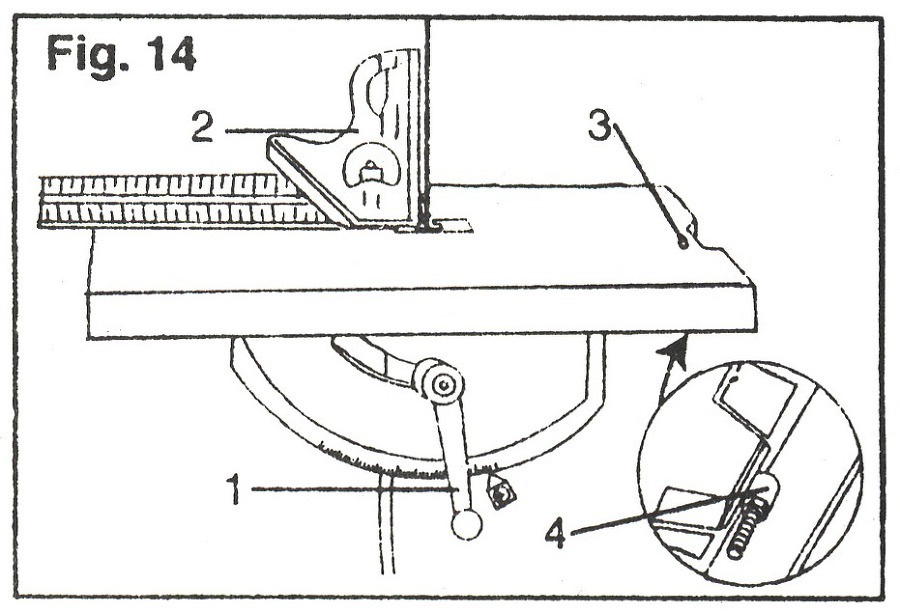
1. Raise the blade guard as far as it will go.
1. 톱날 가드를 최대한 올립니다.
2. Loosen the table lock handle. (1)
2. 테이블 잠금 핸들을 풉니다. (1)
3. Set a combination square (2) on the table and align it with the blade.
3. 테이블에 직각자 (2)를 놓고 톱날에 맞춥니다.
4. Move the table until it is at a 90˚ angle to the blade. Tighten the table lock handle (1).
4. 톱날이 테이블과 90도 각도가 될 때까지 테이블을 움직입니다. 테이블 잠금 핸들 (1)을 조입니다.
5. Turn the zero stop set screw (3) until it touches the frame. Use a wrench to tighten the lock nut (4) under the table.
5. 제로 스톱 설정 나사 (3)를 프레임에 닿을 때까지 돌립니다. 렌치를 사용하여 테이블 아래에서 잠금 너트 (4)를 조입니다.
6. Recheck the adjustments, reset the tilt pointer to the actual correct reading.
6. 조정 상태를 다시 확인하고, 기울기 포인터를 실제 정확한 판독 값으로 재설정하십시오.
Wheel brush (Fig.15)
휠 브러시 (그림 15)

The wheel brush is located inside the housing and helps keep the blade and the wheel free of sawdust and wood chips.
휠 브러시는 하우징 내부에 위치하며, 톱날과 휠에 톱밥과 나무 조각이 없도록 유지하는 데 도움이 됩니다.
1. To adjust, loosen the screw (1) and position the wheel brush (2).
1. 조정하려면 나사 (1)를 풀고 휠 브러시 (2)를 배치하십시오.
2. Tighten the screw (1).
2. 나사 (1)를 조입니다.
Locking the switch (Fig.16)
스위치 잠그기 (그림 16)
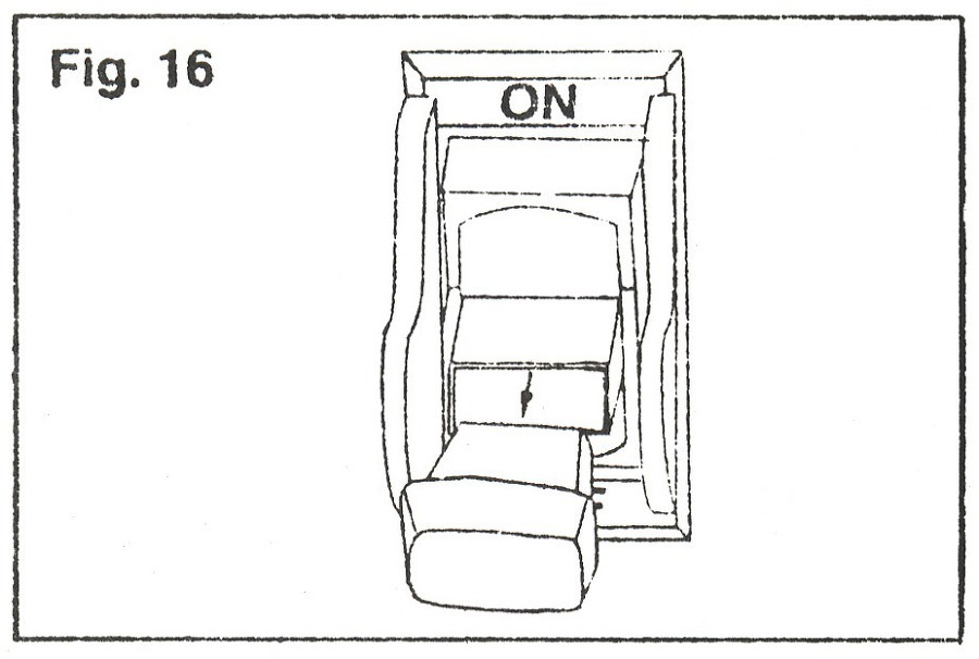
The switch should be locked when the saw is not being used.
밴드쏘를 사용하지 않을 때는 스위치를 잠가야 합니다.
1. Wait until the saw has come to a complete stop.
1. 톱이 완전히 멈출 때까지 기다리십시오.
2. To lock the switch in the 'off' position, remove the yellow switch key from the switch housing. Store it in a safe place.
2. 스위치를 'OFF' 위치에 고정시키려면, 스위치 하우징에서 황색 스위치 키를 제거하십시오. 안전한 장소에 보관하십시오.
3. To turn the saw 'on', insert the yellow switch key into the switch housing and move the switch to the 'on' position.
3. 톱을 '켜기'로 돌리려면, 황색 스위치 키를 스위치 하우징에 넣고 스위치를 '켜짐' 위치로 이동하십시오.
Tilting the table (Fig.17)
테이블 기울이기 (그림 17)

1. Loosen the table lock handle (1).
1. 테이블 잠금 핸들 (1)을 풉니다.
2. Tilt the table to the side until it reaches the desired angle.
2. 원하는 각도에 도달할 때까지 테이블을 옆으로 기울입니다.
3. Check the angle markings opposite the pointer (2).
3. 포인터 반대쪽의 각도 표시를 확인하십시오 (2).
4. Tighten lock handle (1).
4. 잠금 핸들 (1)을 조입니다.
Mitre gauge (Fig.18)
연귀 게이지 (그림. 18)

1. The mitre gauge fence (1) can be turned 45˚ to the right or left.
1. 연귀 게이지 펜스 (1)는 오른쪽 또는 왼쪽으로 45° 회전할 수 있습니다.
2. To set the angle, loosen the lock knob (2) and rotate the fence until it reaches the desired angle on the index scale (3).
2. 각도를 설정하려면 잠금 손잡이 (2)를 풀고 펜스가 인덱스 눈금 (3)에서 원하는 각도에 도달할 때까지 펜스를 돌립니다.
3. Tighten the lock knob (2).
3. 잠금장치 (2)를 조입니다.
Dust chute (Fig.19)
먼지 슈트 (그림 19)

1. The dust chute (1) blows dust away from the user.
1. 먼지 슈트 (1)는 사용자로부터 먼지를 뿜어냅니다.
2. The dust chute opening measures 1 3/4″. It may be connected to a dust collection system.
2. 분진 슈트 열기(부분?)는 1 3/4"(약4cm?)의 폭이 됩니다. 먼지 수집 시스템과 연결될 수 있습니다.
Fence (Fig.20)
펜스 (Fig.20)
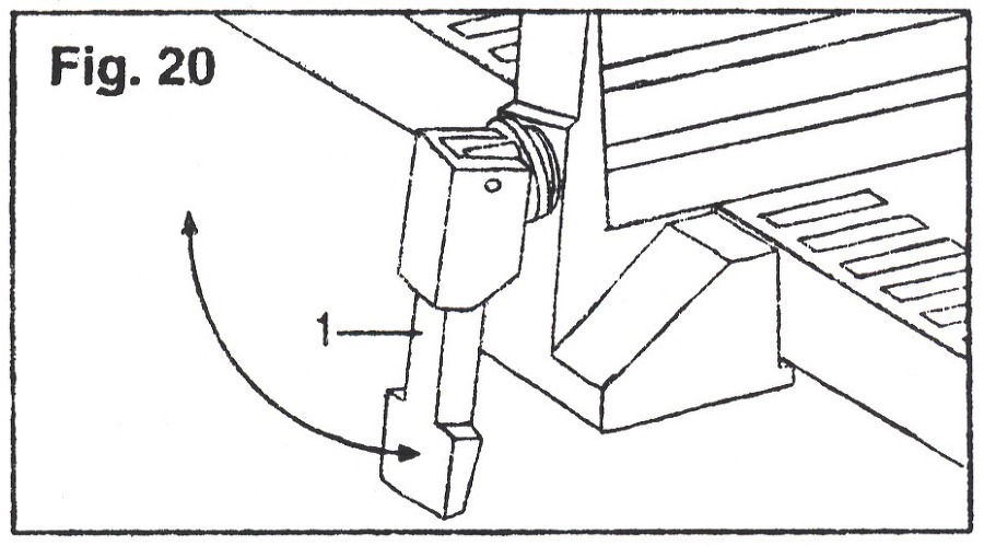
The quick set fence can be moved or locked in place by raising or lowering the lock handle (1).
빠른 세트 펜스는 잠금 핸들 (1)을 올리거나 내림으로써 제 위치에서 움직이거나 고정될 수 있습니다.
Basic operation information
기본 작동 정보
WARNING : To avoid blade contact and personal injury, adjust the upper guard assembly so that it just clears the workpiece.
경고 : 톱날 접촉 및 신체 부상을 방지하려면, 상단 가드 어셈블리(조립부품?)를 조정하여 공작물을 제거하십시오.
For general cutting, follow the pattern lines by pushing and turning the workpiece at the same time. To achieve a curved radius cut, follow the pattern line with the blade while turning the workpiece. The blade should cut in the middle of the pattern line (saw kerf).
일반 절단의 경우, 동시에 공작물을 밀고 돌려서 패턴 선을 따르십시오. 곡선 반경 커브를 얻으려면, 공작물을 돌리는 동안 톱날로 패턴 선을 따르십시오. 톱날은 패턴 선의 중간에서 자릅니다 (톱니 커프).
Use both hands to feed the work through the blade and make sure you hold the workpiece firmly against the table. Use light pressure and do not force the workpiece.
양손을 사용하여 톱날을 통해 작업물을 공급하고, 작업물을 테이블에 단단히 고정하였는지 확인하십시오. 가벼운 압력을 사용하고 작업물에 힘을 가하지 마십시오.
The diameter of your circle cut is determined by the width of the blade. A 1/4″ blade will cut a minimum diameter of approximately 1-1/2″. A 1/8″ blade will cut a minimum diameter of approximately 1/2″.
원형 컷의 직경은 톱날의 폭에 의해 결정됩니다. 1/4"(6미리?) 톱날은 약 1-1/2"(2~12미리?)의 최소 직경을 절단합니다. 1/8"(3미리?) 톱날은 최소 직경 약 1/2"(12미리?)를 자릅니다.
Band saw minimum cutting radius (Fig.21)
밴드쏘 최소 절단 반경(그림 21)

Cutting radius will vary according to blade width and set. The minimum turning radius for the three blades available is :
커팅 반경은 톱날 너비 및 세트에 따라 다릅니다. 사용할 수 있는 3개의 톱날의 최소 회전 반경은 다음과 같습니다.
Band saw selection guide
밴드쏘 선택 가이드

Always use the widest blade possible
가능한 가장 넓은 톱날을 항상 사용하십시오.
NOTE : blade length is 56 1/8″
참고 : 날 길이는 56 1/8 "
VIII. Maintenance
VIII. 유지 관리
WARNING : For your own safety, turn the switch 'off' and remove the plug from the power source outlet before performing maintenance on or lubricationg your band saw.
경고 : 안전을 위해 밴드쏘의 유지 보수 또는 윤활 작업을 수행하기 전에 스위치를 끄고 전원 콘센트에서 플러그를 뽑으십시오.
1. Remove sawdust from inside the housing and blow sawdust out of the motor.
1. 하우징 내부에서 톱밥을 제거하고 모터에서 톱밥을 날려 버리십시오.
2. Clean off the pitch that accumulates on the table, blade guides, and bearings.
2. 테이블, 톱날 가이드 및 베어링에 쌓인 피치(잔유물)를 닦아내십시오.
3. Apply a thin coat of automotive polish to the table top and to the trunnion. Polish for a slick surface.
3. 테이블 위와 트러니언에 얇은 자동차 광택제를 발라 줍니다. 매끄러운 표면을 위해 연마합니다.
4. Remove pitch and dust from the wheels using a stiff brush. Do not use solvents.
4. 뻣뻣한 브러시로 바퀴에서 피치(잔유물)와 먼지를 제거합니다. 용제를 사용하지 마십시오.
5. Replace the wheel tires when worn.
5. 마모 시 휠 타이어를 교체합니다.
WARNING : Replace the power cord immediately if it is worn, cut, or damaged in anyway.
경고 : 전원 코드가 마모되었거나 절단되었거나 손상된 경우 즉시 교체하십시오.
팔콘 밴드쏘 매뉴얼이었습니다.
감사합니다.